Design it. Check it. Build it. A detailed working guide from the first board to dimensioned ribs and full-size cutting templates, written for first-time users with the exact checks experienced builders need.
Updated for Railmora 9.0 rc.364Project format 81 · illustrated with current Railmora screens
1PlanBoards and operating needs
→
2DesignTrack, levels and stations
→
3CheckGuardian and clearances
→
4BuildStructure and templates
LOOK · CLICK · BUILD
Learn Railmora by following the pictures
Start at picture 1. Follow the circles. Stop when you see red.
Green = ready or safeBlue = selectedOrange = second point or review
1
Place your first track
Choose it, point at a green end, then click.
1Open Track & roads
The track tools appear
2Choose Place + a track
A preview follows the pointer
3Touch the green end
Press R if it faces wrong
4Click once
Green means connected
2
Select and move track
Nothing changes until the track is selected.
1Choose Select/move
The pointer is now safe
2Click the track
Blue shows your selection
3Hold and drag
Watch the ghost position
4Release to finish
Press Esc to cancel
3
Connect two ends with Smart Route
Show Railmora where the route starts and ends.
1Choose Smart route
Railmora asks for A and B
2Click end A, then B
Use two open green ends
3Wait for proposals
Green is the safe candidate
4Apply, then Check
Undo removes the whole route
4
Make a smooth ramp
Pick the complete run, enter two heights, then apply.
1Open Heights
Use the four numbered groups
2Choose A, then B
The blue preview shows the run
3Enter start + end
Example: 0 mm → 80 mm
4Apply ramp
Open Profile to inspect it
5
Build a helix
You do not draw a circle first. Railmora builds it from your choices.
1Tools → Layout assistants
Open the Helix page
2Choose limits
Grade, height, shape and tracks
3Create + click an end
The complete helix snaps here
4Check grade + clearance
Use the limiting inner track
Red means stop.Read the message, press Esc if needed, and do not apply until the preview is green.
How to use this guideFirst follow the picture guide above. For a new layout, continue with chapters 01–10 in order. Open chapters 11–14 when the design is ready for 3D and workshop work.
01
The safe order: idea to workshop
Railmora works best when the physical limits are decided before detailed track and scenery.
Outcome
You finish with one checked project whose 2D plan, elevations, 3D views and workshop drawings all describe the same railway.
Create and name the projectUse Project › New, then Save As. Give the file a name you will recognize in backups and exported build packages.
Draw the real footprintCreate every board, module or L-shaped section at its real size. Include gaps, room corners and separate upper decks that physically support track.
Choose scale and catalogueSelect the exact manufacturer and product line before placing track. Catalogue geometry, connector rules, radius classes and flex-stock limits depend on this choice.
Build the operating skeletonPlace the continuous main route first, then station throats, sidings, hidden storage and connections between levels. Add detail only after the main route closes correctly.
Add elevationsSet level heights, ramps and smooth vertical transitions. Recheck after each major change because a safe 2D crossing can still have too little vertical clearance.
Audit before decoratingRun Check and Railmora Guardian. Resolve critical geometry, grade and clearance findings before adding scenery or generating construction.
Inspect, build and exportUse Realistic 3D for the finished scene, 3D Construction for the physical structure, and Build package for drawings, templates and materials.
Before you continue
Boards are locked when their shape is final.
The intended routes have no unexplained open connectors.
Critical Guardian findings are fixed or deliberately accepted and documented.
A named project copy exists before automatic changes.
Simple view keeps the next useful actions visible. Advanced view exposes specialist controls without changing the project itself.
Outcome
You can switch complexity without losing selections, geometry or saved data.
Start in SimpleUse the top View button to keep the ribbon focused on common tasks. The button text follows the active mode, so it shows Simple in Simple view and Advanced in Advanced view.
Open Advanced when neededUse it for detailed geometry, analysis and construction controls. Secondary commands remain available under More when screen width is limited.
Use the main workspacesStart manages the project; Boards defines the footprint; Track & roads edits geometry; Heights controls elevations; Stations adds operational meaning; 3D opens visual and construction views; Check audits the design.
Read the status barThe bottom-left status is the best description of the active tool. Press Esc if the pointer appears to be placing, measuring or editing the wrong object.
Collapse tools on smaller screensHide tools reduces ribbon height without removing the current workspace. Restore it when you need less common actions.
ImportantChanging view mode changes only which controls are shown. It does not simplify geometry, remove advanced project data or bypass validation.
The .rsc project is the source for track, levels, scenery, operation and construction.
Outcome
Your active work and important milestones can be recovered independently.
Save earlySave the new layout before long edits. Railmora can then show a clear file name and keep autosave recovery associated with the project.
Use named milestonesChoose Save As before applying a large assistant proposal, height repair or station redesign. A name such as layout-before-level-2 is more useful than relying only on Undo.
Treat autosave as recoveryAutosave helps after an interrupted session, but it is not your archive. Keep dated copies of important stages.
Recover from a missing network pathIf a NAS or synchronized folder is unavailable, use Save As and select a local folder. Do not close the only open copy first.
Know compatibilityThe current documented project format is 81. Keep an original copy before opening important work in a newer release candidate.
Boards define where track can be supported and where assistants are allowed to place geometry, while city plates provide scenery surfaces.
Outcome
The layout footprint matches the room and cannot move accidentally while you edit track.
Create the board shapeChoose rectangular, round or polygon geometry. Enter exact dimensions when they are known; use handles only for shapes that genuinely need free editing.
Represent every physical deckA board on level 0 does not automatically support track on level 1 or above. Add the actual upper deck, shelf or module footprint on the appropriate level.
Place boards against a datumUse one stable corner or room wall as the measurement origin. This makes exported positions, construction ribs and workshop checks easier to verify.
Lock completed boardsLock each board after its size and position are correct. When you leave Boards with unlocked boards, Railmora shows a reminder with Lock boards and Keep unlocked.
Unlock intentionallyUnlock only the board you are changing. Locking from the reminder is one Undo step and affects only the boards named in the reminder.
Use city plates correctlyCity plates are visible scenery surfaces for buildings and placed objects. They are not a substitute for a structural board under track.
Before you continue
All intended track lies over a supporting board or deck.
Board dimensions match the workshop material, not only the visible grid.
Unlocked boards are intentional before running an assistant.
Railmora uses the selected catalogue’s real articles and connector geometry. Flex-only catalogues are handled as cut stock rather than invented fixed straights.
Outcome
Placed track remains compatible, editable and countable in the material list.
Select the exact product lineChoose the manufacturer, scale and system in the Track palette. Do not connect similar-looking track from incompatible systems unless a supported transition piece is used.
Place from a connectorSelect an article, move its preview to an open endpoint and click or press Enter. Press R to rotate; supported turnouts also use Tab to cycle alternatives and Shift+R for 180°.
Move existing piecesActivate Select/move and click the track. Detached track returns to placement behaviour so it can rotate and reconnect like a new piece.
Use Replace for article changesReplace preserves the intended location while changing a compatible piece. Always inspect the neighboring connectors afterward.
Edit flex as geometryMove endpoints and curve handles to create a continuous transition. Railmora checks heading, length and minimum radius; it does not silently make an impossible flex shape valid.
Understand flex stockFor PECO Streamline Code 55 and other flex-only systems, assistants may use flex cuts as straight or curved geometry. The saved pieces retain the real stock article and length limit.
Split only for productionA long editable flex curve can remain one design object. Split it into physical stock lengths before final workshop export when Railmora reports that production integrity requires it.
ImportantR1, R2 and R3 are catalogue families, not universal millimetre values. Read the radius shown for the selected system.
These tools propose geometry while preserving explicit approval and final validation.
Outcome
You can solve a difficult connection without surrendering control of the rest of the layout.
Choose clear endpointsSmart Route needs endpoints A and B with usable approach directions. Remove accidental nearby open connectors before searching.
Select the search depthBalanced is the normal first choice. Thorough and Maximum explore more candidates and may use the selected time budget on constrained multi-level routes.
Set physical limitsConfirm minimum radius, maximum grade, board containment and clearance. Helix assistance is a fallback after ordinary ramps and detours fail unless you explicitly select a helix mode.
Compare the resultReview endpoint distance, angle, radius, grade, collisions and board fit. A visually smooth preview is not enough if the validation is amber or red.
Use Push & Reflow for local redesignMove the green ghost, use 1, 2, 3 or Tab to compare alternatives, Enter to apply and Esc to cancel. Protected anchors and construction intent remain fixed.
Create parallel routes from a sourceUse Parallel left or right from correctly aligned track. Fixed curves should use the catalogue’s concentric radius family rather than visual alignment by eye.
Before you continue
The result closes both endpoints within the displayed tolerance.
No protected bridge, tunnel or fixed anchor changed unexpectedly.
A fresh Check finds no new collision, grade or clearance problem.
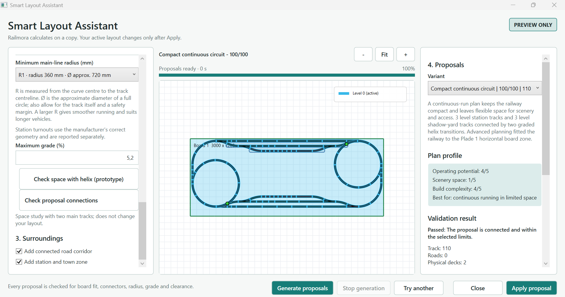
The assistant creates proposals from explicit constraints and calculates on a copy of the project. It is a planning aid, not a promise that every room can produce a sophisticated railway automatically.
The proposal is shown between the constraints and the validation panel. Nothing enters the active layout until Apply proposal is selected.
Outcome
A proposal can be compared safely and changes the live project only after Apply proposal.
Prepare the footprintFinish and preferably lock the boards first. The assistant evaluates the actual board shapes and selected level count.
Enter operating needsSet track system, train length, station and storage capacity, levels, minimum main-line radius and maximum grade. Use realistic values for the available space.
Choose ambition and topologySelect a layout type that matches how trains should run. Automatic variation can compare alternatives, but it cannot invent usable space outside the boards.
Generate and waitThe calculation runs on a copy. Do not start it repeatedly while progress is active. Inputs are remembered when the window is reopened, but replacement approval and old proposals are not.
Read the plan profileCompare operating potential, scenery space and build complexity. Confirm track count, physical deck count, connected networks and validation result.
Inspect large or L-shaped footprintsA proposal should use the requested boards meaningfully. Reject a compact loop that leaves a large branch unused or creates a decorative dead end without an operating purpose.
Apply only a useful proposalUse Try another to compare. Apply proposal only when the route is connected, within limits and suited to the intended operation. Undo removes the applied proposal as one operation.
ImportantMulti-level automatic generation remains an evolving Preview feature. Always run Guardian and inspect the result before construction.
Logical levels organize the drawing; real elevations determine grades, crossings and construction height.
Outcome
The railway rises smoothly and maintains the required rail-top-to-structure clearance.
Create logical levelsUse levels to separate decks and colors. A level number is not itself a physical height; tracks can ramp within a level.
Set exact endpointsIn Heights, select the connected run and define start and end elevations. Keep station tracks and intended level areas flat unless a grade is deliberate.
Reserve transition lengthSmooth vertical profiles need gentle entry and exit curves. Railmora reserves extra length so the nominal grade does not create an abrupt change at a joint.
Build a helix from limitsChoose system, one or two tracks, direction, radius family, rise, grade and clearance. Check the complete diameter including track and safety margin.
Check both helix tracksIn a double-track helix, the inner route is normally steeper. Review both grades and use the limiting result.
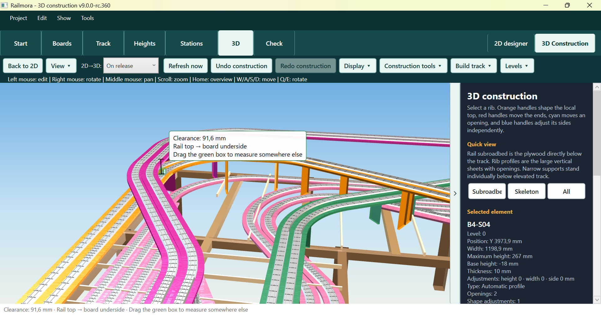
Measure the physical gapAt a crossing, clearance means from the top of the lower rail to the underside of the upper subroadbed—not track center to track center and not level height alone.
Before you continue
The maximum grade respects the project rule.
Height changes are smooth at both ends of each ramp.
Upper subroadbed thickness is included in clearance.
Turnouts are not placed on unsuitable abrupt vertical transitions.
A station is both track geometry and an operating structure with usable lengths and routes.
Outcome
Train length, platform capacity, storage and route direction agree with the physical layout.
Design for the longest trainUsable length must fit the complete train between fouling points, not merely inside the visual platform.
Build the throatChoose the actual entrance turnout and intended level. Keep ladders on the correct height and verify every retained connection after optimization.
Name consistentlyUse clear station and block names that remain understandable in route lists, reports and future automation.
Assign directionDistinguish one-way and bidirectional sections. Define ENTER, IN/STOP and occupancy contacts according to their real detector purpose.
Treat hidden storage as service equipmentProvide inspection openings near hidden turnouts and enough reach for cleaning and rerailing. Capacity is not useful if the tracks cannot be maintained.
Test routesUse route and train tools to verify that intended movements connect and that trains can pass or meet where the design requires it.
Guardian groups repeated findings, explains the physical consequence and can preview safe repairs without editing the project first.
Outcome
Critical risks are either repaired, shown for manual work or consciously accepted as documented deviations.
Run a fresh auditOpen Check and run Railmora Guardian after track, height or board changes. Filters help separate critical, warning and suggestion findings.
Start with the lowest crossingThe guided height pass works from the physically lowest track upward. It establishes clearance before refining dependent height jumps and grades.
Preview the repairReview current and proposed heights, affected ramp, maximum grade and before/after joint smoothness. The live project changes only when you apply.
Use Fix all safe for repetitionGrouped grade, jump and clearance families are recalculated after each improvement. The full accepted batch becomes one Undo operation.
Understand a blocked repairA proposal is blocked if full-layout validation shows a new or worse clearance, grade or connected-height problem. It may become possible after a neighboring safe repair.
Skip or force deliberatelySkip leaves the project unchanged and continues. Try to fix anyway is available only for a locally valid but globally risky proposal and requires explicit confirmation; Guardian audits again afterward.
Accept an intentional exceptionUse Accept as intentional only when the physical design genuinely permits it. The deviation remains documented in construction reporting.
ImportantGuardian is conservative. Branches, fixed height anchors and insufficient ramp length can still require manual geometry changes.
Realistic 3D is the presentation and spatial-review view; the 2D Designer remains the geometric source of truth.
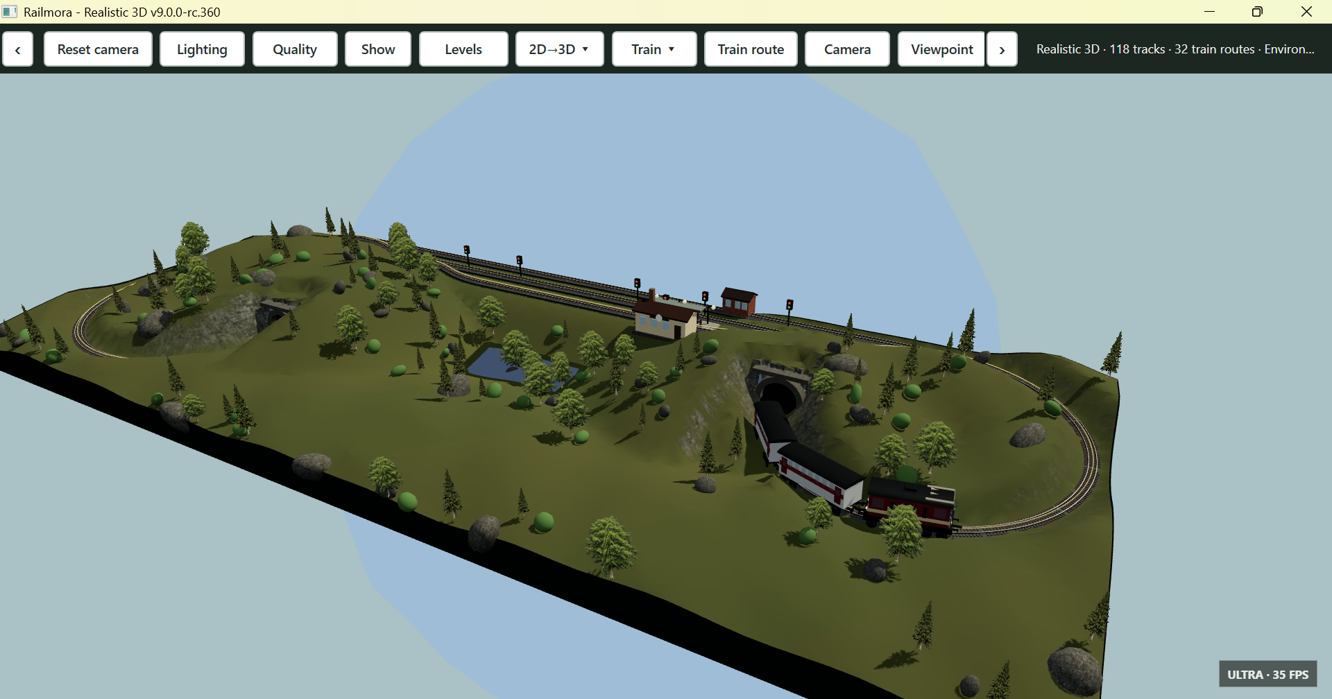
Realistic 3D combines the checked route with terrain, tunnels, buildings, scenery and train presentation.
Outcome
You can inspect how trains, terrain and scenery work together without cluttering technical 2D editing.
Choose visible levelsShow only the levels needed for the scene. Large layouts remain more responsive when hidden decks and unnecessary objects are turned off.
Classify trackSelect tracks and assign open, bridge, tunnel or hidden status. Remove an incorrect classification without rebuilding the track geometry.
Rebuild terrain after tunnel editsTerrain generation updates portals, cuttings and openings together. Portal apertures follow the track and the terrain seam is stitched around the opening.
Place scenery from the intended surfaceBuildings and objects need an appropriate track reference or city plate. Completed scenery is deliberately hidden in the technical 2D Designer and 3D Construction views.
Focus an objectUse the project overview or scene selection to open Realistic 3D, reveal the object’s level and frame it automatically.
Inspect with a trainChoose a train route, normal view or cab ride. Use saved viewpoints for repeatable checks of portals, platforms and tight scenery.
Tune performanceLower quality while editing dense terrain or many objects. Restore higher quality for final presentation images.
3D Construction converts the rail plan into editable frame, subroadbed, rib profiles, supports, fascia and plates.
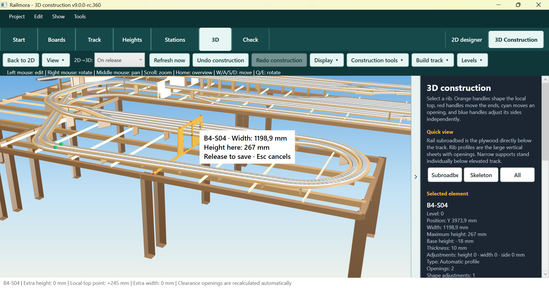
Rib B4-S04 is selected. Its workshop identity and measurements remain visible while its local profile is edited.
Outcome
The structure can be inspected and adjusted before any timber is cut.
Generate after geometry stabilizesFinish boards, routes and heights first. Regenerate construction when those source elements change.
Isolate the layer you needUse Display and Quick view to show subroadbed, skeleton or all. Hide expensive layers while editing a large construction.
Select a ribClick a rib to see its stable ID, level, board position, width, maximum height, base height, thickness and opening count.
Edit with live dimensionsOrange handles shape the local top, red handles move ends, cyan moves an opening and blue adjusts its sides. The pointer label shows the live width or height; release saves and Esc cancels.
Use precise dimensionsOpen Precise dimension for numeric work. Long labels and out-of-range values are explained rather than silently accepted.
Measure a crossingUse the green clearance probe under an upper track. It reports the local distance from the lower rail top to the underside of the upper subroadbed using interpolated ramp geometry.
Inspect hidden structureUse X-ray, sections, focus and level visibility to confirm openings, supports and crossings that are difficult to see in the full model.
Recover the cameraPress Home to fit the construction overview if the camera has moved or zoomed too far away.
The build package turns one verified project into workshop instructions, material information and printable cutting aids.
Outcome
Each selected rib and track template can be identified, measured, printed and matched back to the layout.
Open Build package after checkingGenerate exports only from the saved project you intend to build. Unresolved critical findings remain visible as build blockers.
Choose content and levelsSelect rib templates, track templates and the exact levels to include. All and None make large projects easier to configure; an empty level choice is rejected when templates are enabled.
Read the print estimateBefore export, Railmora calculates rib pages, track pages, flex pages and total A4 pages. Jobs above 200 pages receive a clear warning.
Use the rib dimension overviewEvery rib begins with a scaled workshop drawing. It shows the stable rib ID, miniature board location, outer width, maximum height, perimeter, material thickness and base height.
Measure every opening from edgesCut-outs are described from the left and bottom datums. The drawing gives opening width and height, distance to the right edge and remaining wood above—without requiring X/Y/Z interpretation.
Print the following tiles at 100%The next A4 pages form the full-size 1:1 cutting template. Disable Fit to page. Verify the printed calibration ruler before joining pages.
Join pages by coordinatesRegistration marks, overlap and stable sheet coordinates identify neighboring pages. Empty track sheets are removed automatically; the visual selector shows which pages contain track.
Use the cut legendBlack indicates the outer cut, red an opening cut and green support marks. Check the part ID before transferring a template to timber.
Plan stock sheetsOptional rib nesting places real profiles and openings on standard or custom stock sheets, with edge margin, part spacing, grain direction, rotation choice and remaining-area estimate.
Follow the workshop sequenceBuild step by step moves through plan review, boards, frame, track beds, track laying, electrical preparation and final test running. Progress changes the guide state, not the layout geometry.
Before you continue
PDF print scaling is 100% / Actual size.
The calibration ruler measures correctly on paper.
Every physical part carries the same stable ID as the drawing.
Oversized ribs are redesigned or handled deliberately; they are never assumed to fit a stock sheet.
Performance, troubleshooting and reporting a fault
Most problems can be isolated by reducing the view to the active task and preserving a copy of the project.
Outcome
You can continue safely or provide enough evidence for a reproducible correction.
Cancel the active toolPress Esc when selection, placement or measurement behaves unexpectedly. Confirm the status bar before trying again.
Reduce visible workHide unused levels, terrain, scenery or construction layers. Use On release for 2D↔3D synchronization on large projects and Manual for exceptional layouts.
Wait for calculationsSmart Route, generation and grouped Guardian repair can use their full search time. Use the available Cancel or Stop control rather than starting a second run.
Check locksIf geometry will not move, confirm Select/move is active and inspect track, level and board locks.
Save a diagnostic copyUse Save As before reducing or changing a problem layout. Keep the original .rsc untouched.
The status bar remains the final authority for the active tool. These are the conventions used across the main workspaces.
Ctrl+N / Ctrl+O / Ctrl+SNew, open and save
Ctrl+Z / Ctrl+YUndo and redo
Esc / EnterCancel / place or apply
R / Shift+R / TabRotate / rotate turnout 180° / cycle alternative
Ctrl+click / Shift+clickChange multi-selection / select connected range where supported
Ctrl+C / Ctrl+V / Ctrl+DCopy / paste / duplicate
DeleteRemove the selected objects
Home in 3DFit the complete view
W/A/S/D and Q/E in 3DMove and rotate the camera
3D mouseLeft mouse edits or rotates according to the view, right or middle mouse pans, and the wheel zooms. Read the instruction strip in the active 3D window.
English is the maintained master. Danish, German, French and Dutch terminology follows the application, while release-specific limitations remain visible instead of being hidden.